CHP Lighting Display System
This is a display board used for emulating and displaying the emergency lighting patterns the California Highway Patrol uses on their patrol vehicles. Having built similar projects previously, this version allowed for many new features.
System Overview
Many different features are included in this project, which are listed below.
- CHP Flash Patterns, with accurate replication of all patterns
- Vehicle Lighting, with controls for most common functions
- Sound Effects, including vehicle horn and siren sounds
- Keypad Interface, used for controlling patterns and vehicle lighting
- Custom Microcontroller, swappable between different display boards
- Multiple Display Boards, to replicate the many vehicles used by the CHP
System Components
This system has many different separate components which all come together to achieve the goals of this project. All involve custom firmware and hardware designed and built specifically for this project. The firmware was written in C++, and the hardware was designed in KiCad.
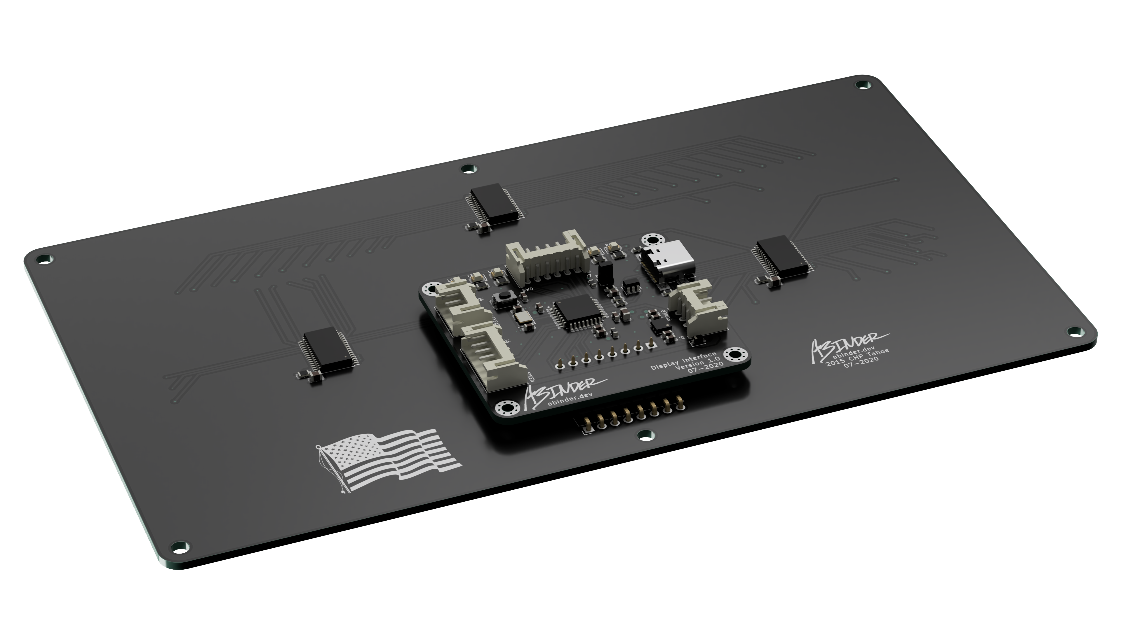
Display Interface

The Display Interface is the main brain of the project. All of the components connect to it and are powered by it. There are connectors for main power input, a sound effects board, a keypad, DFU/control, and a main Display Board connector.
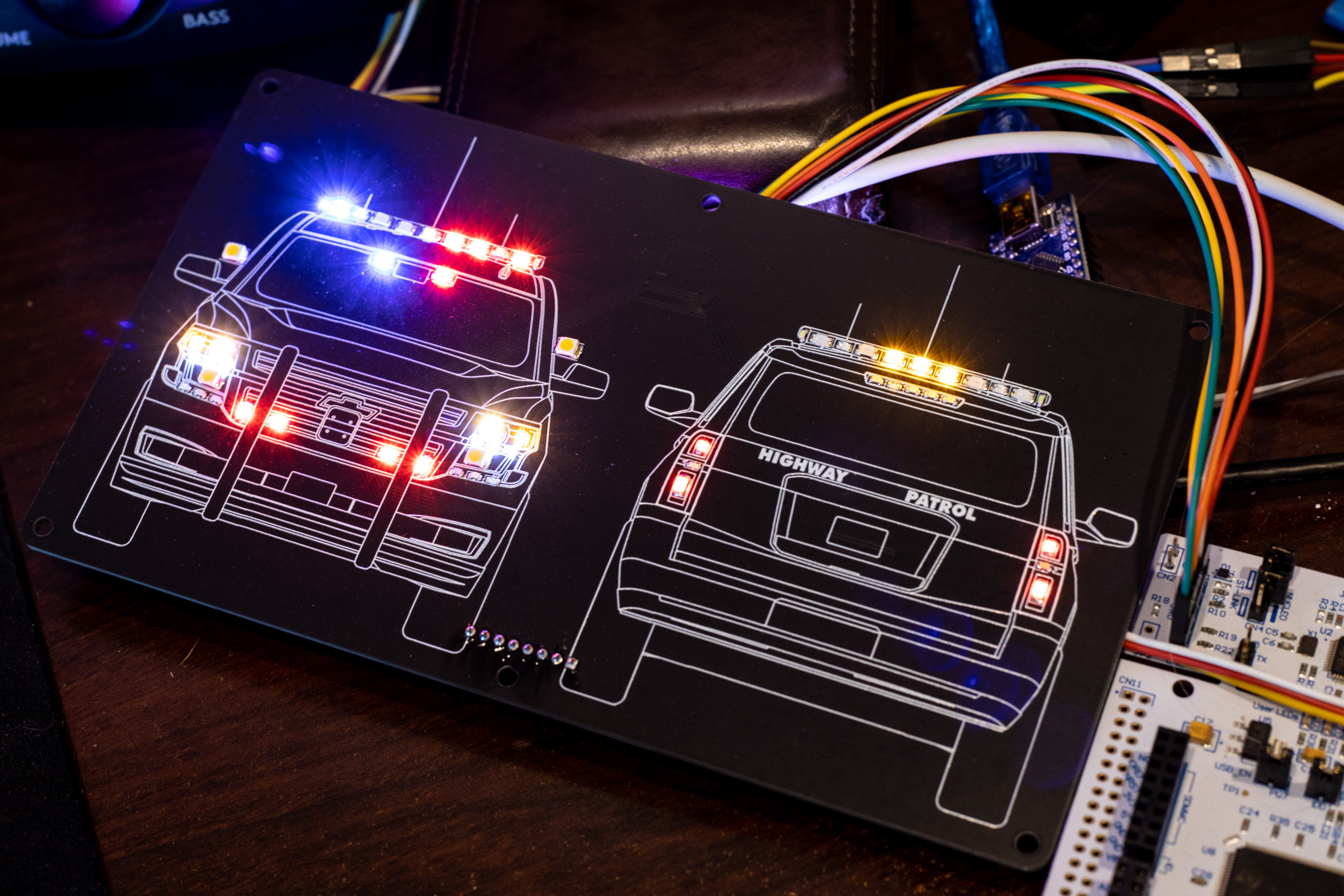
Display Boards

The Display Boards have line art silkscreen of patrol cars customized to match CHP vehicles, with surface-mount LED’s to represent vehicle lights and emergency lighting. They also have some light circuitry on the back, used for driving the LED’s.
Both white and black PCB’s are used to represent the different vehicles used by the CHP. The line art of the vehicles was customized for this project, but not drawn from scratch for this application.
The Display Interface plugs directly onto a Display Board, powering it and sending data. The LED drivers allow for individual brightness control of each LED, making it simple to emulate the incandescent bulbs used in vehicles.
Keypad Controller

The Keypad Controller connects to the Display Interface which allows control of patterns and vehicle functions, such as gear, headlights, turn signals, and more. The Keypad Controller connects to an Arduino Mega which then connects to the Display Interface.
It also has LED indicators to identify different patterns and modes. It runs some the same firmware as the Display Interface, and communicates with the display interface with UART.
Sound Effects
Sound Effects are played using an Adafruit Audio FX Sound Board with Amp. There are sound effects for the CHP-style siren (wail, yelp, air horn, and a manual wail), as well as a stock-style car horn.
USB Control
Optionally, the system can be controlled with USB via a virtual COM port. A simple application can be used to send the same Serial commands the Keypad Controller sends.